The first step to start working with EPLANT-Piping is the generation of a Project. To do so we must create a folder with a name less than 10 characters, that will be converted to an EPLANT-Piping project. For the example we shall use TEST. Please note that the same example is already installed in the EPLANT-Piping main installation directory with the TEST name. We will create it elsewhere.
After the folder creation, we have to run, at least once, the EPLANT-Piping Data Base Module from the corresponding option in the Start / Programs menu:

In the Data Base Module main window we then select:

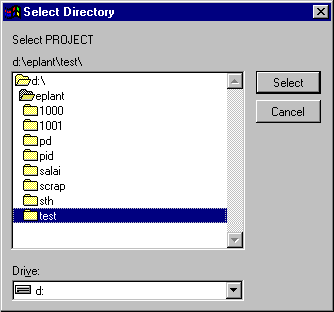
The following dialog box will appear allowing us to select our new project TEST.

The system warns that this folder is not an EPLANT-Piping project and prompts with the following dialog box:

We select ACCEPT and EPLANT-Piping will create several new folders, nested in the TEST project folder.
DBF: Stores all Data Base files.
ISOE: For Isometric drawing generation and isometric Header and Format drawings used in the project.
PLE: For 2D Plan Drawing generation.
SPOOL: For Isometric Spool Drawing generation and spool isometric Header and Format drawings used in the project.
TIP: For Typical Assemblies Drawing generation.
LINK: To store External Files linked to project models.
EXP_NAV: To store 3D models converted to NavisWorks import.
PCF: To store files exported to PCF format and related setup files.
SUPP: To store the blocks of Typical Support Structures, their related Templates and the 2D Plan generated for the project.
EXP_PDMS: To store 3D models converted to PDMS format (to be used in conjuntion with the EPLANT-PDMS Converter).
After these preliminary steps we are ready to start working in our project.
If you are running the EPLANT-Piping Evaluation Version go directly to the TEST.DWG in the TEST directory and open it with a double click to start AutoCAD. The EPLANT-Piping session will be automatically started.
The EPLANT-Piping Graphic option in the Programs task bar can also be used.
To work on an already created project you must select the menu option:
File/Open project
After you create a project, EPLANT-Piping automatically recognizes it when it is opened.
Opening a project created with a previous version of EPLANT-Piping the system will warn that it will procede to update project files without any loss of information. In case the project uses a Project Catalog, all the local system files will be updated too.
3D models must be placed in the main project directory, in this folder there is always present the ACAD.LSP (and ZWCAD.LSP) file that loads the EPLANT-Piping and initializes the working session.
The best practice is to start AutoCAD (or ZWCAD) from the Windows Explorer, with a double click over an existing DWG file in the project directory, to ensure that the ACAD.LSP (or ZWCAD.LSP) is always read.
It is also possible to select the EPLANT-Piping Graphic option, which can be found in the Start / Programs menu.
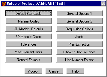
When a project is opened its settings can be easily changed.
During the project generation all project parameters receive a default value. Unless very special cases, most of the setting don't require any change.
Let's look to the main settings:


DEFAULT STANDARDS
Defines the default dimensional standard that will be used (ANSI, DIN, etc.) and Symbology
standards.
MATERIAL CODES
Three different Material Codes can be set to work with: one is automatically generated based on an
algoritm and two more may have arbitrary definition and will use translation tables.
3D MODELS: DEFAULTS
Several parameters are set here: default codes for implicit element generation, default
gasket and welding thickness (they may be changed during component generation), default
surplus length in pipe segments, minimum pipe length during Automatic Pipe Generation.
3D MODELS: COLORS
Colors assigned to objets generated by EPLANT.
TOLERANCES
Setting Tolerances used for different purposes: Dimensional Tolerance and
Angular Tolerance to define
the tolerance to automatically cut elbows (example: if the tolerance is 1 degree and our
elbow makes an 89 angle, the system places a 90 degree, but if our elbow makes an 87
degree angle the system will cuts the elbow to 87 degree).
Roundings in lengths.
MEASUREMENT UNITS
Setting Lengths in Dimensioning and MTO either in mm or imperial and the Thickness unit when
thickness is used instead of Schedule.
GENERAL FORMATS
Setting Solid Primitive Graphic in 3D Models: it can be either Wire Frame Mesh or Solid.
The file size does not change, but with Solid the screen regeneration speed can be very slow.
Setting for Copying Dimension to Diameter 2, which allows to use the Second Diameter field to
show the first dimensional parameter (used for gaskets and Nipples), format of CSV files.
GENERAL OPTIONS 1
Defines: Project Language (description language used in Reports), Project Name, External Data
Association link, Additional Codes and Cost tables location, Secondary Schedule Generation mode,
Insulation generation.
GENERAL OPTIONS 2
Enables/Disables several options: enforces Unique Line and Equipment across the whole project,
Spool generation mode: explicit in 3D models or from piping class, shared DBF tables access in networks,
3D Model Material Generation, Out of specification in component placing, saving to project setup
from graphic, Enable component dimension manual input, PCF Export and others.
REQUISITION OPTIONS
Sets the criteria for revision assignment to material requisitions and others.
JOINTS
To enable and configure Joints codes used to designate weldings.
PLAN EXTRACTION
Allows to change default values assigned to extraction Layers and their colors.
ELBOWS, THORUS, CONES
Controls the definition of surface objects that are generated in 3D models.
LINE NUMBER FORMAT
This option allows specifying the piping line number format used in the project, to
be able to process them according to their format. The isometric drawing name can be
set as a specific combination of the line name parameters or reading its name from the P&ID
Line List table.
The File/System Setup option, opens the same window as in
Project Setup, with the difference that all setting changes will affect only
those project that will be created in the future. The interface language (that is the
language that is used to interact with the user through menus and prompts) can be changed
here. Currently only English and Spanish are supported.
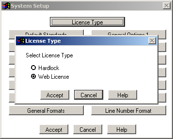
The System Setup is also used to set the License Type, either based on a hard-lock
connected to the computer or a Web License that requires an internet connection:

Last updated October 16th, 2020.