Although piping plans could be obtained as direct views of the 3D model, the
symbology would result confusing, because it is optimized to deliver a good 3D looking.
For this reason, when the 3D model is finished we must perform the view extractions that
will be used in the plan drawing, completing the views with the required notes. While the
first operation is completely automatic, the second requires some manual work.
The plan extraction can be performed with any spatial orientation. The symbology used to represent piping components can be simple or double line and can be the exact projection of the 3D representation or using an associated parametric symbol. It is generally completed with dimensions and notes.
To generate plans, four different phases will be required:
- 2D Views Definition
- 2D Views Extraction
- Adding Notes and Dimensions to complete the drawings
- Drawing update for 3D Model changes
Plan extraction is only done in drawing files placed in the \PLE project directory. A void drawing file must be generated in that directory.
Upon entering it with an AutoCAD session, all relevant 3D Models are attached as Xref files, defining the insertion point as the WCS 0,0,0 and selecting Overlay as the Reference Type (to avoid cyclic reference between drawings).
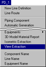
We select from the menu the following option:

If the current drawing has no defined 2D Views yet, and this is surely the case with a new file, the following warning will appear requesting authorization to create one:

To be able to continue we must accept the creation of a 2D View with the Accept button. The following window will open:
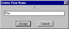
Aftern changing the defaul name 1 and selecting the Accept button, the following window opens to define Size and Position of the View. Each View must then be associated with a corresponding Viewport in a Layout. In our example we shall input the values shown in the window:
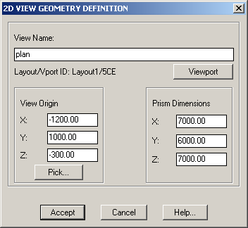
This window is used to define: Name, Dimensions and Position of the current view. All of them can be changed now or any time later.
Each View can be imagined as a Prismatic Volume placed in a specific place of the drawing. The 2D Plan extractor generates a plane representation of each object contained in the volume associated with the view, projected with respect the local Z axis of the viewport associated with each view.
The size of each extraction volume can be also modified using standard AutoCAD commands, such as Modify Property. In the same way, its position can be modified with the plain AutoCAD Move command.
Closing this window with the Accept, the main 2D Plan Extraction dialog box appears:
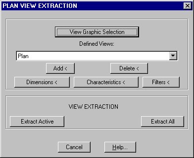
In case of defining another view the Add button can be used. To delete an existing view both the Delete button or the AutoCAD Erase command (outside this command) can be used.
Selecting the Characteristics button the following dialog opens:
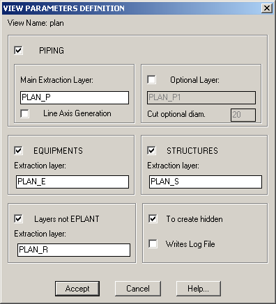
This dialog defines which types of objects generated by EPLANT are to be extracted and how, for the active view selected in the main window.
For each component type: Piping, Equipment, Structure and NOT EPLANT elements an extraction layer is proposed. These names are built using the View name as a prefix plus the suffix defined in the project setup for each type of objects. The Notes added with the corresponding EPLANT command will be placed on the same extraction layer plus the suffix _TXT or _TXTL in case of a reference line.
In the PIPING section the extraction layer for Piping Components is specified, along with and Optional Layer that can receive the projection of all piping components having a nominal diameter less than specified in the Cut Optional Diameter. It is also possible to generate the piping line axis.
For EQUIPMENTS and STRUCTURES the command uses one extraction layer each.
If the Layers NOT EPLANT option is checked, all elements directly drawn with CAD are also processed.
Coming back to the main 2D Extraction window, selecting the Filters button, different types of conditions can be imposed to include or exclude part of the objects to be processed.
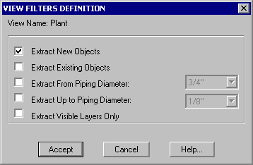
New Objects are those generated by EPLANT by default, the Existing Objects are objects with their status modified with the command:
PD_UTI / Varios / New/Old Conversion
Our View will appears as follows:
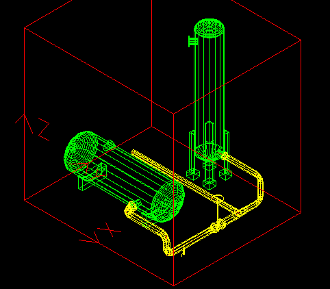
Coming back again to the main extraction dialog, selecting the Extract Active button the view selected in the menu is generated and with the Extract All button all views are generated. The process is fast and the execution time varies linear with the drawing dimensions.
Before to generate elements in a given layer the command shows the total quantity of elements already there, if any, and allows to delete all of them.
After a modification of the 3D Models the view extraction must be repeated to automatically update the drawing of the corresponding views.
Once the views are generated, we enter Paper Space selecting the Layout1 folder. To be the first time, the Layout Setup Page will be displayed. We use this window to set the Plotting device, the paper size (A2 in our case), dimensions in mm and Scale 1:1:
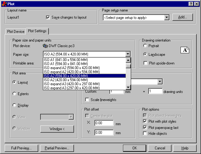
Being now inside the Layout will follow the sequence:
Our drawing will now look this way:
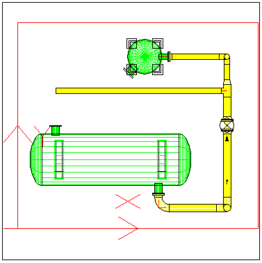
To set Layers ON and OFF in the Viewports it is very convenient the following command:
PD_UTI / Display Layers / Viewports
or from the toolbar menu:

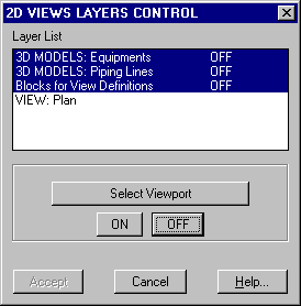
Inside the menu, the xref's 3D Model layers will appear as Lines, Equipments and Structure
groups (if any) along with the layers of the Blocks for View Definitions and each of the defined 2D Views
in the current drawing.
This command allows to turn ON and OFF those groups of layers selected in the menu. In our
case, let us select Line and Equipment layers in 3D Models and the Blocks for Views Definitions to set them OFF.
Selecting the Viewport border, the Accept buttom will be enabled to enforce the changes.
Our drawing will now look:
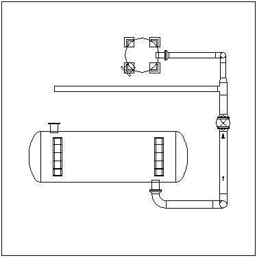
First of all we should check the text settings for annotations. We take the command:
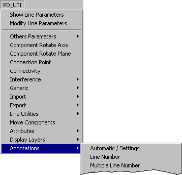
or from the toolbar menu:

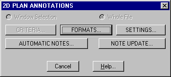
With the Formats option, the format of each note can be modified for the current project. Texts for Notes are configured with the Settings button. With the Automatic Notes button, Tag Notes will be automatically placed for all the elements that will be prompted to be selected.
To place any other note the way is always the same: note type selection on the menu, selection of the component to be annotaded, selection of the point where to put the note. For example: Line Number:

The annotate command will automatically take care of Model to Paper Space switching during object/note_position selection, in case the project in setup to place notes in Paper Space (default).
In case of modifications of the project 3D Models after issuing 2D Plan drawings, the sequence is as follows:
IMPORTANT: the Automatic Note Update assumes that between different revisions, the name of 3D model files are the same. If a model is renamed, all related notes will be deleted.
To plot a plan drawn in Paper Space select the Viewport border, take the Modify Properties AutoCAD command and set the Hide Plot parameter to Yes to perform a hidden line removal on objects in Model Space.
In the Plot Setup window we must also mark the Hide Objects options to hide objects in Paper Space, such as tag boxes that are created in two different Z planes on purpose.
Last Updated October 16th, 2020.