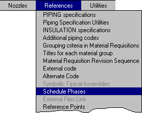
3D Models can be used to graphically represent any construction or operational Phase assigned to Equipments and Piping Lines.
The procedure is the following:
Project Phases definition is done in the data base module with the option:

For Equipments, the corresponding option is selected in the Equipment/Line menu. The following window opens, which allows to load Phases assigned to Equipments. In this example, two phases are defined, corresponding to 50% and 100% of the equipment construction.

The Scheduled Color is used to change to that color those equipments which on the analysis
date have the corresponding phase completed, with regards the Scheduled Date. If there
are more than one completed phases, the last one is considered.
The Delay Color is used to change to that color those equipments that have a phase with
the analysis date falling between the Scheduled and Real dates, in case they have the
Real date defined.
Equipments that have not any phase completed or delayed are set off.
Dates to Equipments phases are defined by the option:
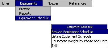
that opens the following window, where Scheduled and Real dates for each equipment and phase can be loaded. The Real date is used only if delays have to be analyzed, otherwise is left blank:

This table contains all Equipments inside all 3D models of the project and is automatically updated. It is also possible to load for each equipment its weight and painting area to automatically compute the Total weight an area by phase and date with the option:
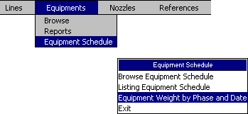
that opens the following window:
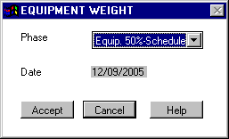
A report to a text file will than be generated including only those equipments that, for the selected phase, have a date less or equal to the analysis date. The Total weight and area for those equipments are also computed.
Dates assigned to each Line Phase are defined with the option:
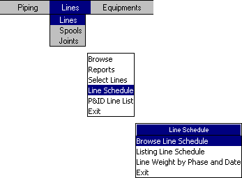
that opens the following window, where Scheduled and Real dates for each line and phase can be defined. The Real date is used only if delays have to be analyzed, otherwise is left blank. In this example, two phases are defined, corresponding to the completion of all line Spools and to the Whole line:

This table contains all Lines defined inside all 3D models of the project and is automatically updated. The weight and painting area to each line is also automatically computed. With the following option the Total weight an Area by phase and date can be computed:
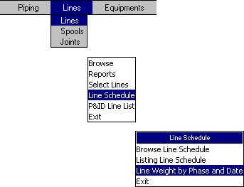
that opens the following window:
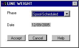
With the Accept button, a report to a text file will be generated including only those lines that, for the selected phase, have a date less or equal to the analysis date. The Total weight and area for those lines are also computed. Each phase is assigned to the whole line, so in this example, the line weight is always the weight of the whole line.
Once equipment and line date scheduling are completed, from a 3D model opened with an EPLANT-Piping session (it can have other models attached as xref), the following command can be executed:
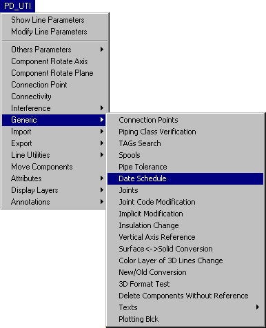
that opens the following window:
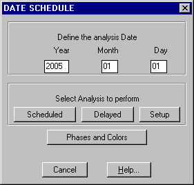
Selecting the Scheduled button, the command searches for each equipment and line if there is a phase with its Schedule date finished by the analysis date. For these Equipments and Lines it assigns the color corresponding to each phase. Those Equipments and Lines that have not any phase completed are set off.
Selecting the Delay button, the command does the same as the previous option, but controls also if there are equipments and lines with analysis dates falling between scheduled and real dates. In this case, the color for delays corresponding to each phase is used.
Selecting the Setup button, all equipment and line layers are reset on and changed to the project setup colors.
Last updated October 16th, 2020.