
To begin working with the graphic module, a void AutoCAD file must be created, or copied
to the main project directory, that will be named SAMPLE.DWG. To work in this file
with EPLANT it is convenient to open it from the Windows Explorer with a double click.
In this way we are sure that the ACAD.LSP file in the same directory will be read. This
in turn will load the EPLANT-Piping system and start the EPLANT-Piping environment.
It also possible to run the EPLANT-Piping graphic module from the corresponding option
in the Start / Programs menu: this option opens the drawing file TEST.DWG with the
tutorial example already done in it.

 EPLANT-Piping Tutorial: Generation of a 3D File Model (48sec)
EPLANT-Piping adds three new menu bars to the standard AutoCAD menu, from which all commands can be selected.
In this example only one file will be used for both Equipment and Piping. In bigger projects, equipments are generally placed in one o more separate files and the piping in other files. The interaction between those files is attained using them as external reference. This strategy has two objectives: not to work will large files and to distribute the work between more designers that are working at the same time in the same project.
EPLANT-Piping assumes that the unit of length is the millimeter, because the dimensional tables are loaded with that unit.
We'll begin with the generation of the Horizontal Vessel TK-001 from the example, let's go to:
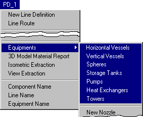
EPLANT-Piping comes with a set of predefined equipments those dimensions and position can be input interactively. The user can add new equipments using a parametric definition or building them from elementary pieces.
 EPLANT-Piping Tutorial: Horizontal Vessel Generation (1min 3sec)
In the same way the Vertical Vessel of the example can be generated.
Alternatively most of the Equipment commands can be selected from the Equipment ToolBar:

Once an equipment is generated, its elements can be modified any time with the command:
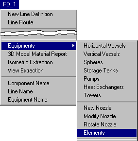
or we can also select it from the Equipments ToolBar:

A dialog box will appear with all the primitive solids available for equipment building. In case of modifying an existing element, it will be selected with the Graphic Selection button that will display in the dialog box the selected type and its current parameters. The parameters can be changed and the Modification option will be selected.
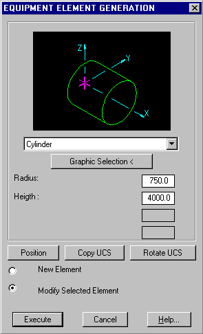
The same command can be used to generate new elements to be added to an existing equipment.
To generate nozzles for equipments that don't come with them already, the following option is selected:
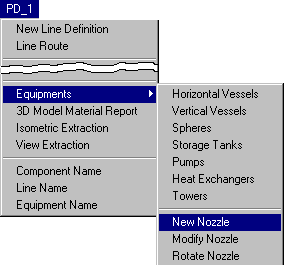
or from the Equipments ToolBar:

The command will prompt to select an equipment to which the nozzle will be added, and afterwards the following dialog box is displayed:
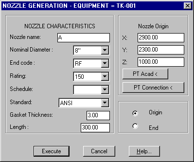
The meaning of the parameters in any dialog box can be consulted with the Help button. With respect to the choice between End and Origin look at the conventions in the following figure.
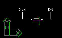
Nozzle Position coordinates are expressed in the current UCS and the Nozzle is generated with its axis coming out from the equipment, aligned along with the positive X axis.
Following its generation, the nozzle can be rotated around any of the current UCS axis, selecting the Rotate button in the dialog box that appears after its generation. Selecting this button, the following window opens:
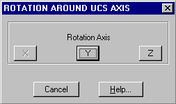
In our case, we select the Z button to rotate the nozzle in the direction of the negative Y axis. We can graphically select the angle with the mouse (set ORTHO ON) or typing 180. We exit this dialog box with Cancel.
 EPLANT-Piping Tutorial: Equipment Nozzle Generation (47 sec)
Each equipment has automatically assigned to a different layer.
There is a set of handy commands to control layers visibility. The most used allows to
set on and off the equipment layers based in the Equipment Name:
PD_UTI/Display Layers/Equipments
or from the toolbar menu:

Executing it, the following window appears:
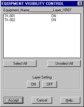
This window shows all equipments ordered by name, giving the control to set on or off each individual equipment. All equipments defined in the current file and in the attached files as XREF are displayed.
In: PD_UTI/Display Layers we can found other useful options. The most used are accessible from the toolbar menu:

At any moment new elements can be added from an existing equipment. To this aim the PD_1/Equipments/Elements option can be used. It displays the same dialog box used to modify an existing element. Select the required type and define its dimensions and position. On exiting the dialog box the element will be generated.
Selecting an existing element, its characteristics are recognized, allowing to modify them or to copy the same element to a new position.
An element generated in this way doesn't belong to any equipment, to associate it to an existing one, the option PD_1/Equipments/Add is used. The following dialog box will appear:
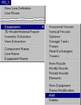
Select the equipment to which the elements are to be assigned (they can be already had assigned to another one or to none) and on exiting from this dialog box with the Execute button, the elements to add can be selected.
To delete an equipment element or nozzle simply use the AutoCAD command ERASE.
 EPLANT-Piping Tutorial: Add / Delete Equipment Element (1min 32sec)
At any time the name of an existing equipment can be modified with the PD_1/Equipments/Modify Name option.
At any time, any characteristics of an existing nozzle can be modified with the PD_1/Equipments/Modify Nozzle command or the same from the toolbar menu:

The command prompts to select the nozzle and, the same window used to define the nozzle, will open with the parameters of the selected nozzle.
It is also possible to rotate an existing nozzle with the PD_1/Equipments/Rotate Nozzle command or the same from the toolbar menu:

If a new equipment not included in the predefined types has to be generated, and a parametric definition is not justifiable, it can be defined generating new elements with the PD_1/Equipments/Elements option, then creating a new equipment name with the PD_1/Equipments/New option, which displays the following dialog box:
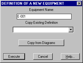
Where we load the new equipment name. Then we can assign this equipment to those elements just created, as shown before.
In the same dialog box there is also the Copy from Diagrams button, that can be used when the Process Diagrams are generated with the EPLANT-P&ID, in this case a selection window will display all equipment names coming from P&IDs.
A set of commands is available to interact with equipments: Copy, Move and Rotate.
These commands can be selected from the menu:
PD_1/Equipments/Copy
PD_1/Equipments/Move
PD_1/Equipments/Rotate
These commands prompt to select an equipment and the corresponding geometrical parameters.
To delete an equipment the AutoCAD command ERASE can be used, but to the EPLANT its name will still be defined. The correct way is to select the command: PD_1/Equipments/Delete that allows selecting the equipment to delete, by name or with a graphic selection.
To purge Equipment definitions no longer used, for example after deleting several
Equipments using the Erase AutoCAD command, the following command can be also used:
PD_UTI/Line Utilities/Line-Equipment Definitions Delete.
A Status code can be assigned to each Equipment using the command:
PD_1/Equipments/Modify Status which displays the following dialog:
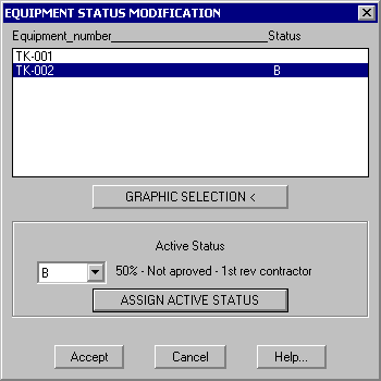
Status codes and associated meanings can be configured for each project. This information can be extracted to an XLS file using the data base module.
 EPLANT-Piping Tutorial: Equipment Utilities: Copy, Move, Rotate (1min 9sec)
Last updated October 16th, 2020.