The EPLANT-Piping generates piping isometrics using an automatic procedure, from the piping lines contained in 3D models. This process is called Isometric Extraction and generates a new file for each line.
Isometric files are 3D drawing files. The lines are represented with the same orientation in which they are drawn in the 3D models, but using adimensional symbols and with a scale deformation for better visualization.
Isometric can be automatically generated with Format, Header, MTO listing, Dimensions and Notes. Each process has its separated settings and can be redone in any moment directly from the isometric file, because it contains the same information as the 3D model from which it is derived.
The isometric of a piping line can be generated in one file or being automatically separated in several sheets, each in a separated file. In the case of spools, each spool is placed in a different file.
To do the extraction, select the menu option:
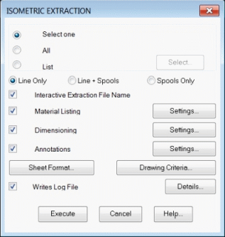
PD_1 / Isometric Extraction and the following dialog box will appear:

The upper part of the window is used to define the lines that will be extracted.
By default the first option Select one is checked. In this case, exiting with
the Execute button, the command prompts to select a line, it displays its name and prompts
to confirm.
The All option automatically selects all lines of the current 3D model.
The List option allows to select the lines to extract, from the complete line
list.
The bottom part of the window allows to set the way in which the extraction will be carried out.
The active view at the moment of the extraction must be equal to the isometric view required for the isometrics, because the format and all additional information will be placed on that view.
Selecting the Execute button, the command extracts all selected line one at a
time, generating its graphic representation in a .DWG file placed in the ISOE
project directory.
If the Interactive File Extraction Name option is checked,
the command will prompt for the extraction file name, generating a default name using
the format rule set in the project configuration line format option. It can be accepted or
modified. If the option is not checked, the default name is used and is a file with
the same name is already present, will be overwritten without warning.
If the Piping Spool option is checked in the project setup, then in the dialog box
the Line + Spools and Spools options will be enabled to allow generating
spools of the extracted line also.
Each spool is written in a separated file in the SPOOLS project directory.
The name of each spool file has the first part with the same name of the corresponding
isometric file, followed by the spool code. It can be modified interactively as the
isometric name.
If during the extraction a connectivity error is found, that is a lack of connection between contiguous components of the line, the extraction continue with a warning, but only a part of the line will be extracted. In this case we must check the connectivity using the command Connectivity Check.
Let's see now the extraction of the 8"-H-600-001-A1 line of our example:
 EPLANT-Piping Tutorial: Isometric Extraction of Line 8"-H-600-001-A1 (1min 9sec)
The main parameters that control the extraction can be set from the graphical application and can be either stored in the project setup or being used only as a test in the current graphic session. There are two buttons in the extraction window: the Sheet Format opens the following window:
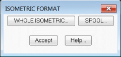
Selecting the Complete Isometric, the following window opens:
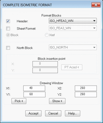
that allows to set the block names used to:
These blocks must be in the project isometric generation directory (ISOE) and must be defined with their origin in the bottom leftmost point.
In our example we'll use the predefined blocks, to A3 format.
Selecting the Spool button a similar window opens to modify spool settings. In this case the prefixes for Spool Headers and Formats are SPL_H and SPL_F respectively. Spool Headers and Formats are stored in the project spool generation directory (SPOOLS).
The Drawing Criteria opens the following window:
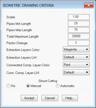
It is used to define:
 EPLANT-Piping Tutorial: Isometric Drawing Area Definition (49sec)
The Isometric Material Take Off is automatically generated during the extraction process. It can be regenerated in any moment from the inside of the isometric file. It consists of a header block and text lines, one for each different material. It is very easy to change the format and content of the listing.
From the main Isometric Extraction window, selecting the Settings option corresponding to the Material Listing, the following window will open:
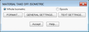
The MTO generation from an isometric file is activated with the menu option:
PD_ISO / MTO which opens a window similar to the previous one:
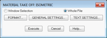
In this case, with the Execute option, the MTO is generated.
The Format option allows to modify the report format, selecting the fields that will show up in the report, their relative position and the header block. It is very advisable to configure the report format being in an isometric drawing, to be able to test it interactively. It opens the window:
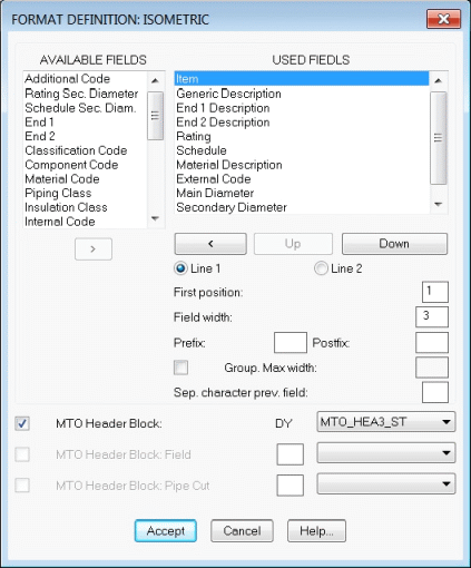
If the report uses a header block, it must be a block placed in the project isometric
symbology directory and have a name prefix MTO_H.
The report itself is made up by text lines that are generated downward starting at the report
origin, defined in the General Seting option.
The fields included in the report can be placed on two different text lines. The fields
belonging to the first line come first, followed by those to be placed on the second line.
If in the second line there is no information por a particular item, that line is skipped.
Several fields can also be grouped together to trim trailing spaces. Follow the indications
on the Help button.
If the report format has to be changed, the following procedure can be used.
Selecting the General Settings button, in the first window, we can configure other parameters:
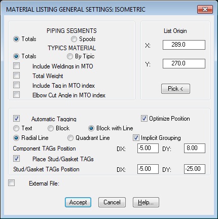
In the case of report format modification, the report origin point will have to be
modified also, to place the report at the right position with respect to the header block.
Inside an isometric drawing we can set the origin also with the Pick button.
In this case it is also possible to modify text parameters and executing the MTO to check
the exact definition of the report.
The Include Tag in MTO index option allows to differenciate those materials only
different for the tag value itself. In this case the Tag field must be addeded in the format.
The Elbow Cut Angle in MTO index option allows to differenciate those elbows only
different for the Elbow Cut Angle value, if present. In this case the Elbow Cut Angle field
must be addeded in the format.
The report automatically generates also implicit elements associated with flanged ends, that is gaskets and studs. These elements don't show up explicitly in the 3D models and are generated using rules.
Selecting the Text Settings button, in the first window, we can configure other parameters, mainly related to the text used in MTO.
After exiting any of these setting windows with the Accept option, the following dialog box will open:

With the Accept option the new settings will be written in the project setup file, ensuring in this way, that all users will take these setting in the future. With the Cancel option the new settings will be active only in the current drawing session: the new setting will be lost opening another drawing file or terminating AutoCAD. This option is used during tests.
For Spools the Sheet Format can be different from the isometric of the whole line, as well as different Material Report Format and Text settings can be used.
 EPLANT-Piping Tutorial: Isometric Format Modification (1min 13sec)
The isometric can be automatically dimensioned during the extraction or any time directly in the isometric drawing.
From the main Isometric Extraction window, selecting the Settings button corresponding to the Dimensioning option, the following window will open:
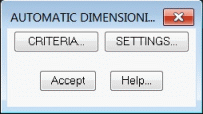
Dimensioning from the isometric drawing is activated with the menu command:
PD_ISO / Automatic Dimensioning that opens a window similar to the last one:
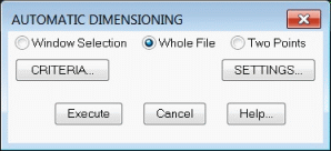
In this case, pressing the Execute button the dimensions will be generated.
The Criteria option allows to modify the dimensioning rules. It opens the following window:
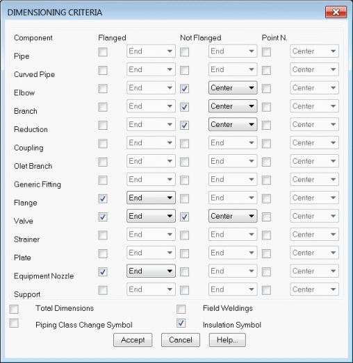
Components are grouped using their class. To each class, three different conditions can be set:
Only those checked classes are dimensioned, unless the component is a pipe segment with an unconnected end that will be dimensioned all the same.
Pipe segments that are skewed with respect to the absolute reference axis by an angle greater than the tolerance for dimension projections will be dimensioned in their projections also. To set this tolerance value, go to the project setup in the General Options. Pipes that has a vertical slope below the skew angle and above the slope setting will receive a slope symbol with the indication of the slope % value.
The Settings option allows to set other dimension parameters, as the text style used for dimensions and the dimension layer:
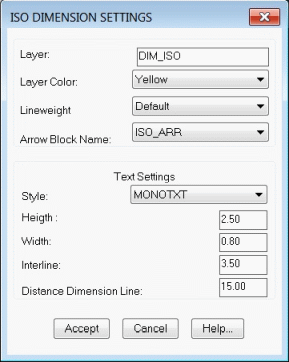
Dimension elements are blocks that can be rotated, deleted and generated again. To generate them directly in the isometric drawing, the same automatic dimension command can be used, along with the Two Points option or the manual dimensioning, that allows to dimension between any point and orienting the dimension at will. This last command can be activated from the menu at: PD_ISO / Manual Dimensioning.
The isometric can be automatically annotated during the extraction or directly in the drawing file.
From the main Isometric Extraction window, selecting the button Settings corresponding to the Annotations the following window will be opened:
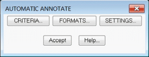
The generation of notes from the isometric drawing is activated by the menu option:
PD_ISO / Annotations / Automatic - Settings that opens a window similar to the last
one:
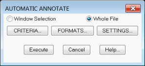
In this case, with the Execute option the annotations are generated.
The Criteria option allows to modify the ruling used to place notes. It opens the following window:
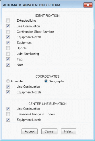
These notes are those that can be placed automatically. From an isometric drawing we can also place other notes, selecting them from the menu.
 EPLANT-Piping Tutorial: Isometric Manual Annotation (13sec)
The Formats option allows to define each note type format, including the
notes that can only be placed interactively:
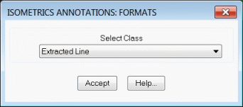
Selecting the required option the corresponding dialog box will opens:
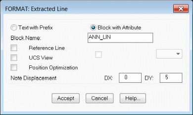
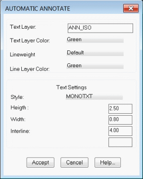
The Settings option allows to set other annotating parameters, as text and drawing layer:
The isometric representation is generated using the symbology blocks contained in the project isometric symbology directory, configured in the project setup (default \PD\ISO). Each 3D piping component has an isometric symbol associated to it, different when changing the end code. The user can modify those symbols, and can also use a different symbology directory.
The block name has the first part of the name equal to the Generic Code (three
characters) plus the end code of the end 1 (up to four characters, generally two), for
example GATRF is the block name of the symbol of a gate valve with flanged RF ends.
Valve operators are the only exception, whose names are made only with the component
code.
For flanged end only, the conventional RF end code is used in place of the real one.
If the end code associated to the second connection point is different from the first one,
typically for flanges and olets, the isometric symbol name will also have the second
end code added to it.
If during the isometric extraction the system can't locate the required block, a warning is issued and the special DUM_ISO block is used. In this case, the required symbol must be defined and the isometric extracted again.
Each new symbol must be generated as a special block using the menu command: PD_ISO / Block Definition, from a 3D model or isometric file. It prompts to select the component code and its end codes (only the first end code is to be specified if the second one is equal to the first):
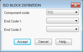
Following that, the Center must be selected, as well as each Connection Points and select the elements comprising the symbol.
The following references must be taken into account:
To maintain symbol consistency, it is convenient to respect these rules or modify all components with similar ones.
Isometric symbols are inserted in the drawing file with scale equal to 1, unless specified another value in the Drawing Criteria option.
If an isometric symbol is not defined with the EPLANT command, for example is a simple AutoCAD block, during the extraction will be discarded with an error message.
To define an isometric symbol the following sequence can be used as a guide:
The following animation shows how to generate a reduction tee with BW ends isometric symbol, using the same symbol for GR ends and taking the BW ends from another component.
 EPLANT-Piping Tutorial: Isometric Symbol Definition (3min 43sec)
In the case of Cut Elbows the isometric symbol is automatically generated using the corresponding "half elbow" symbol. These symbols have the following names: iso_e_bw, iso_e_sw, etc. depending on the end code.
IMPORTANT: to generate isometric symbols, always use a void drawing file or, at least without any AutoCAD solids elements, to avoid generating symbols with incorrect structure that will not be accepted during their use in an isometric extraction.
Few components (those with the ISO_PDL field = 1 in the COD.DBF table) require a dynamic definition of the isometric symbol. Refer to the Technical Manual chapter 7 for details.
Isometric drawings are 3D files and contain the same data present in the 3D models from which they are originated.
Each isometric symbol is inserted in the plane corresponding to the related 3D component.
In some cases, it can be convenient to rotate the symbol around the piping axis, to change
its graphic appearance.
Both PD_ISO / Cmp/Dim Rotate 90 and PD_ISO / Cmp/Dim Rotate ang menu
command can be used. The first one rotates the component by 90 degree and the second one
by a specified angle, or from the toolbar menu:

These commands can also rotate Dimension and Annotation elements with respect the piping axis.
To move Notes and Tags identifications the PD_ISO / Move TAG - Notes menu command can be used. The same command can be selected directly from the toolbar menu:

The isometric can be deformed with the AutoCAD STRETCH command, to beautify and make the
drawing more clear. The dimensions are not modified. All piping components are
blocks except pipe segments that are LINE elements, that will be modified by the STRETCH
command.
The MOVE command can also be used and modify then the pipe segment that will became
disconnected, moving one of its ends.
In both cases the modifications must be done being in the WCS.
If the Stretch command is used, it is convenient to delete before all additional information placed around the isometric itself. It can be used the PD_ISO / Delete Notes menu command.
If the piping line has closed loops, during the isometric extraction some of them can be drawn open instead. To close them the Close Loop menu command can be used. This command prompts selecting the elements to move, the pipe end to stretch and two points that will be joined. The command stretches the pipe along with one of the current UCS axis. If the desconnection is along more than one axis, the command is taken again to join along other axis, selecting a suitable pipe end to stretch.
Depending on the piping configuration and the isometric active view, some parts of the line can be superposed and difficult to see. Typically in the case of 45 degree piping. In these cases, simply rotate the view a little, for example using the following command available in the toolbar menu:

as to obtain a clear representation and than rebuild all the additional information using the menu PD_ISO / Reconstruction command that will delete all but the isometric and reinsert the format and header blocks and regenerate the MTO, Dimensioning, Annotations and the North symbol if required.
 EPLANT-Piping Tutorial: Isometric Modifications (29sec)
Last updated October 02, 2024.