
All 3D piping components are parametrically defined. EPLANT-Piping comes with an very
complete predefined library of components, but the expert user can modify these definitions
and generate new ones as he or she likes.
The Technical Manual included in the system
documentation has all the necessary information.
Once the line route is generated we can generate on it the 3D components, that are selected in a generic way from the menu:

Alternatively, the most used components can be placed selecting them from the following toolbars:


There are two different ways to place a component, using a line route or another component as a reference. Generally, a combination of both methods is used, depending on the geometry.
As a first step, we should verify the Line Active Parameters, selecting the menu option:
PD_UTI / Show Line Param
or from the toolbar menu:

A window with the parameters associated to the Line Active Parameters will appear. During piping component generation, it is very important to check that in COMPONENT GENERATION the Graphic Selection option is checked, to force building the components using the selected line, unless the special cases when the current active parameters values are required.
In our example we first start placing the flange connected to the A Nozzle of the TK-001 vessel and the following elbow and, from there on, we generate the remaining line route, as explained in the previous chapter. So, we delete all line route segments and take the menu command:
PD_1 / Flanges / Welding Neck
or from the toolbar menu:

The prompt will appear:
We accept the default with an Enter. The following prompt is:
SNAP TO A CONNECTION POINT - Select point
We select a point on the A nozzle. The command prompts now to select a line,
in this case the 8" line (it is the line that will be used to generate the component: remember
that we selected a nozzle, the system cannot derive in this case any line from the selection).
The snap cross on the nozzle connection point will appear and a Welding Neck flange is
automatically generated, connected to the nozzle.
When a flange is generated selecting a connection point, the system chooses, not only the
geometrical orientation of the flange with respect to the snapped point, but also the
connection point, analyzing the end code of the face of the snapped point. The next
prompt will appear:

We stop the flange placement, selecting the No button.
 EPLANT-Piping Tutorial: Flange Generation Connected to a Nozzle (40sec)
In our example we place now an elbow connected to the flange, selecting the following menu option to generate 90 degree long radius Elbows:
PD_1 / Elbows / 90 LR Elbow
or from the toolbar menu:

The following window opens:

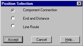
We have to modify the default selection (that for Elbows is Line Route) to Component Connection and we exit with the Accept button. The command prompts:
SNAP TO CONNECTION POINT - Select point
We select a point on the recently placed flange. A snap cross appears on the welded connection of the flange. This point is automatically selected, instead of the flanged point, the nearest connection point from the selection point not withstanding, because the elbow under placement has Butt Welded ends. A 90 degree long radius Elbow will generate connected to the flange.
The most common Elbow placement mode is to Line Route. In this case, the elbows automatically orient themselves along the line. It is also the only way to generate a cut angle elbow.
Directly connecting the elbow to a component, as we are doing, we have to expect that the elbow orientation may be not the correct one. In the window, following the component generation, we select the Rotate button:

selecting to Rotate the elbow, if the ORTHO setting is ON, the rotation angle is easily indicated with the mouse and the elbow is placed in the correct position. We continue inside the command to place the following elbow. In the Position Selection window, that is shown below, we select the End and Distance option:
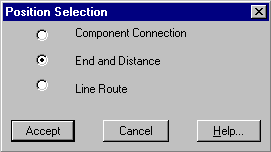
We select a point on the elbow, on the side of the continuation of the line. The following window opens:

We keep the default Center selection (in this case the distance is taken from the snapped elbow center) and type the value 2000 on the Distance edit box. We exit this window with the Accept button and in the following window, we select the Center option:
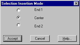
In this way the second elbow is generated with its center at 2000 mm from the first elbow center. Also in this case, we select the Rotate button and rotate the elbow pointing down. We stop the generation with the No button.
 EPLANT-Piping Tutorial: Elbow Generation Connected to a Flange (1min 13sec)
In our example we continue routing a segment of the line from the last placed elbow center, selecting the Line Route command, as seen in the previous chapter:

and in the following window we select the Continue Center option. Selecting the last elbow, from its center we will continue with the same sequence already seen in Line Rute, drawing the 6"-H-600-002-A1 Line Route also.
 EPLANT-Piping Tutorial: Line Route from an Elbow (1min 47sec)
In our example we need to place a reducing tee. We use the menu command:
PD_1 / Branch / Reducing Tee
or from the toolbar menu:

The following window opens:
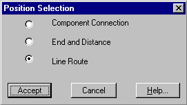
In this case we accept the default Line Route option and the command prompts:
Select Branch line
As in this case, the branch line is different from the manifold line, the graphical selection
of the branch is enough to instruct the command to generate a 8"x6" Reduction Tee on the
line with the greater diameter. If both sides were of the same line, the command would prompt
to select the branch diameter from a window.
The Tee will orient itself along the line axis and with the characteristics of the
manifold line class.
 EPLANT-Piping Tutorial: Reducing Tee Generation (36sec)
If the project has Branch Tables defined, an alternate method is to select the Branch Table option in the menu an let the system place the corresponding component:
PD_1 / Branch / Branch Table
 EPLANT-Piping Tutorial: Use of the Branch Table (1min 7sec)
To place the 8"x6" Concentric Reducer use the menu command:
PD_1 / Reductions / Concentric Reduction
or from the toolbar menu:

The Position Selection window will appear:

In our case we check the Component Connection option and select the Tee end. In the secundary diameter selection window we choose 6".
The same sequence is followed to place the Half Coupling with 1" of diameter.
PD_1 / Branch / Half Coupling
or from the toolbar menu:

In Position Selection, the most convenient option in this case is Line Route: we select a point on the horizontal segment and type 800 as the reference distance with respect the segment end. After its generation, with the Rotate button, we rotate the Half Coupling downward because it is the connection point for a Drain Typical Assembly.
 EPLANT-Piping Tutorial: Concentric Reduction / Half Coupling Generation (1min 26sec)
In our example we finish the elbows placement using the Line Route as reference for the first elbow. We select the command:
PD_1 / Elbows / 90 LR Elbow
or from the toolbar menu:

The following window opens:

In this case we accept the default Line Route option and the command prompts:
Select line near the elbow
It is indifferent to select a line or another, it is enough being on a line route segment
nearest to the elbow vertex. In that segment end the other segment end must be present.
The line, piping class and diameter are automatically derived from the line route selection.
The following window opens:

With No or Esc the command is stopped.
For the next two elbows that follow the reduction, and as a result they have 6" diameters, we have the option to either modify the Line Active Parameters to force the 6" diameter use or to place the remaining components with selections on existing components, as to be able to automatically take a different diameter with respect the line definition one.
A better way to place elbows on line routes is to use the Automatic Placement Command than takes automatically into account diameter changes due to existing components already placed on the selected line. This way will be used in the following movie.
 EPLANT-Piping Tutorial: Automatic Elbow Generation on a Line Route (53sec)
To place an 8" gate valve use the menu command:
PD_1 / Valves / Gate
or from the toolbar menu:

In the Position Selection window, we select the End and Distance option and then select a point on the Reducing Tee on the side toward the TK-001 vessel. In the following window we type a distance of 1000 and after that, the Selection Insertion Mode window will appear:

where the reference with respect to the valve is taken to set the distance. In our case we'll take the Center of the valve as reference.
 EPLANT-Piping Tutorial: Valve Generation (32sec)
To place the 8" flanges use, as already seen, the menu command:
PD_1 / Flanges / Welding Neck
or from the toolbar menu:

The prompt will appear:

We accept the default with an Enter. The following prompt is:
SNAP TO A CONNECTION POINT - Select point
We need to place flanges now against the valve and one more on the nozzle B of the TK-002 vessel. For the valve, we select both valve ends, one after another. We continue selecting the nozzle. In this case the command prompt a line selection, to be used to place the flange on (we select the 8" line) and the following message will appear:

that allows to change the flange under generation diameter, from the line nominal one (8") to the selected nozzle one (6"). We accept the change and the 6" flange will be generated. We stop with the No button.
 EPLANT-Piping Tutorial: Flange Generation (45sec)
To place pipe runs between existing components, the following menu command is used:
PD_1/Pipes/Automatic Pipes
or from the toolbar menu:

The following window opens to allow selecting the line on which the pipes are to be generated:
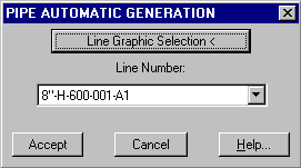
Exiting the window with the Accept button, the command generates all pipe runs between existing components that are needed to complete the line. Any unconnected components with a distance less than the Minimum Pipe Length (defined in Project setup) are shown. Current settings of the Line Active Parameters are not taken into account.
 EPLANT-Piping Tutorial: Automatic Pipe Generation (16sec)
Pipe segments can also be placed manually one by one. This way will be needed to place the 6" run. Use in this case:
PD_1/Pipes/Pipe
or from the toolbar menu:

The command prompts for the first point selection option, that in our case, will be modified to Line Route to be able to pick the reference to the 6" line route, in the opposite end with respect to the Reducing Tee:
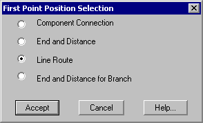
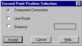
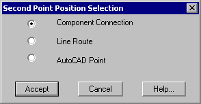
The Second Point Position Selection option follows, that can be a distance also, using the orientation of the first point. In our case, we leave the default to Component Connection and select the 6" Reducing Tee end:
 EPLANT-Piping Tutorial: Generation of a 6" Pipe Run (30sec)
There are three possibilities: the first end of the pipe is the starting point of a pipe to pipe branch, the second end is the arriving point of a pipe to pipe branch or both ends are pipe to pipe branches.
To begin a pipe to pipe on the first end, the last option must be selected:
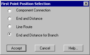
After defining the placement point, the following dialog opens to allow specifying a reduction branch:
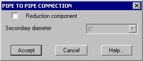
The second end may be placed anywere, using the most convenient reference:
In case of selecting Component Connection and snapping to another pipe, the following dialog appears:
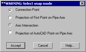
In this case, Connection Point: snaps to the nearest connection point to the selected pipe.
Projection Firts Point over Pipe Axis: the First selected Point is projected over the selected
pipe axis as the Second Point.
Axis Intersection: the point will result by the intersection between the axis
exiting from the First selected Point and the Pipe Axis selected as Second Point. This option is only
available if the first point snapped is a Connection Point or Line Route.
Projection of AutoCAD Point on Pipe Axis: the point can be anyware and the pipe axis refers to the pipe
selected with the second snap.
In the last three options the following dialog will then appear:

With the Cancel option the pipe will be cut up to the tangent with the existing pipe surface, on the contrary with the Accept option, the result will be the following:
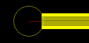
In both cases the connection point of the new pipe will be exactly on the selected pipe axis to guarantee conectivity between them.
In the following movie (that does not belong to the example developed in this tutorial, but is has been included for clarification) several different methods of placing are shown:
 EPLANT-Piping Tutorial: Pipe to Pipe Generation (3min 58sec)
Elbows, Flanges and Pipes can also be automatically generated with the command:
PD_1/Automatic Generation
or from the toolbar menu:

The following window opens that allows to select the line on which the automatic generation of these components is required:
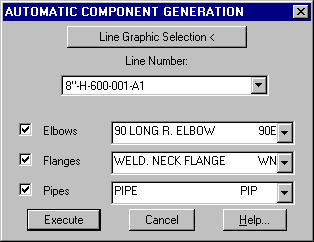
Selecting a line, this command analyses the specification class of the same line and loads the Elbow, Flanges and Pipe menus with the components of the each type contained by the line class. The required components for generation are selected on each menu and with the Execute button the generation is performed. The rules for generation are the followings:
Elbows: an elbow of the specified type is generated in each line route
intersection.
Flanges: a flange is generated on each free flanged end.
Pipe: a pipe segment is generated between each pair of unconnected component
facing each other having compatible connection ends and with a distance greater than the
Minimum Pipe Length. In those cases when the distance is less than the minimum, the pipe
is not generated, but a cross is drawn and a warning sign is displayed with the total
number of unconnected points found.
The system allows to generate 3D Piping Typical Assemblies working in the TIP project directory. In this directory, each 3D model corresponds to a typic. Each model can contain only one piping line, with an arbitrary name. The dwg model file name is used as Typic identification: when inserting a Typic on a model line, all Typic components are assigned to the receiving line. All other characteristics remain unchanged.
Let us copy, to our TIP project directory, the two typics that are found in the TIP directory of the TEST project that is generated during the system installation.
To insert a Typic on a piping line, the following menu command is used:
PD_1 / Generic / 3D Typical Assemblies
or from the toolbar menu:

The following window opens allowing to choose the Typic to insert:
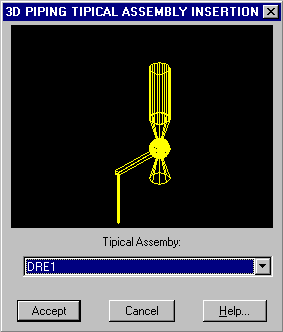
After exiting this window with the Accept button, we have to select the Position Selection mode, as with any other component, to be able to place the Typic on a line:

The Typic insertion point is selected as the nearest connection point to the WCS origin in the Typic definition drawing file. It is advisable to move the whole Typic as to have the Typic origin in the 0,0,0 origin, to avoid any ambiguity.
 EPLANT-Piping Tutorial: Placement of a Drain Tipical Assembly (60sec)
To place a text note in isometrics, the Note 3D component can be used, connected to the connection point where the note will point to. It is available in the menu:
PD_1/Generic/Note
Once the Note is placed, selecting it with the Component Name command it will enable the Note/Detal button:
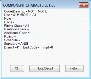
Selecting that button, the following window will open, allowing defining the text to be placed as a note and also the name and path of a block to be placed in the isometric drawing as a Detail:
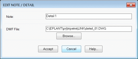
In this example, the note specifies to place the block detail_01.dwg as a detail drawing. Selecting again the Note component, it will show both parameters:
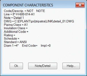
When all 3D components are placed it is necessary to check the line connectivity, that is, to verify that there are not void spaces between them nor superpositions.
Each component has snappable points in its ends, the so called connection points, the connection points of adjacent components must be coincident to verify for connectivity. A correct connectivity is necessary to be able to extract piping isometrics.
Connection points only can be displayed with an EPLANT command, from:
PD_UTI/Connection Points
or from the toolbar menu:

Selecting a component with this command, the nearest connection point is snapped and marked with a cross. In case of a welding thickness or gasket thickness we can see how the ends of contiguous components are separated of that thickness.
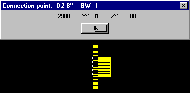
 EPLANT-Piping Tutorial: Connection Points (23sec)
Selecting an existing component during component generation, the nearest connection point is automatically selected, unless in the case of a flange selection. In these cases the system snaps to the end with the same end code that will be generated. This option is very handy because flanges can be selected approximately: the system will always choose the correct side to connect.
During the isometric extraction, any connectivity error is informed, but it is convenient to check the connectivity before the extraction, using the command:
PD_UTI/Connectivity Check
The following dialog box is displayed:
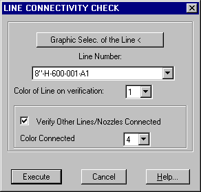
This command allows to verify the line connectivity among its components and detects all connections with other lines and equipment nozzles if any. The other lines and equipments can be in the same drawing file or in attached reference files. The connectivity is generated analyzing the connection points only. The First Component of the Line and any Reference to Vertical Axis are also shown if found in the line.
The color in which the selected line is displayed can be set. If the connectivity of the line is ok, the command will state it and the line is displayed centered in the active screen. If there is a failure in the connectivity, the line is displayed in two parts: the unconnected points lies between the two parts.
Checking the Verify Other Lines/Nozzles Connected option, the command will
automatically detect all connected components that will be displayed in another color
(also settable) and a snap cross on each external connection point.
No matter if the lines and equipments are in freezed layers, the command will detect them
all the same.
In these verifications each step is signaled with the following window:
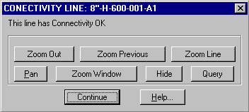
which allows to scan the line with the most convenient zoom option, without exit the command. Selecting the Continue button, the command will go to the following step or comes back to the main window at the end.
If the 3D model is big (many hundred of lines) some seconds are required for the first verification (if the verification with other lines/nozzles is included). This is normal and it is due to the lot of calculations performed in this case.
 EPLANT-Piping Tutorial: Connectivity and Interconnection (48sec)
To resolve a connectivity error the first thing to do is to pin point where the problem arises. If there is a misplaced component (this is the most common case) it can be moved to the right place using the command:
PD_UTI/Components Move
or from the toolbar menu:

This command prompts to select all elements to move (they can be any AutoCAD element), the point that we want to move and the reference point where we want to snap.
If the selection for the Second Point is made on a Rectilinear Pipe, the following window will open:
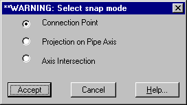
The command here offers the choice between snapping to the nearest connection point, or the following options: snap to the projection of the Base Point over the selected Pipe Axis or to the intersection between the Pipe Axis and the axis passing through the Base Point. These last two options allows to connect a fitting or another pipe to a pipe placed not at the pipe end, but over the pipe axis.
If the project Piping Specifications or some of the dimensions stored in the Dimension Catalog are changed after the 3D model generation, the corresponding components already in place could be outdated. To detect this errors and to correct them, the following command is used:
PD_UTI/Generic/Piping Class Verification
The following setup window will open:
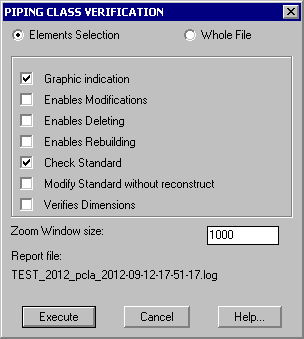
By default this command only verifies differences, without modifying anything unless allowed to. In case of disabling the Graphic Indication only the report file with the found differences is generated. In case of enabling the Graphic Indication, the command stops at any difference found showing them and proposing the appropiate action to fix the problem. The Verify Dimensions option is used to detect and automatically rebuild those components that has their dimensional tables changed.
It is very important to carry out this operation to assure absolute consistency between project piping specifications and the 3D model.
If Line Definitions are modified after having generated components of the same lines, there is a command that found all possible inconsistencies and allows to easily fix them:
PD_UTI/Generic/Piping Lines Verification
The following setup window will open:
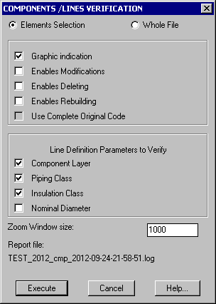
By default the command only verifies differences, without fixing them. Disabling the Graphic Indication only the report file with the found differences is generated. In case of enabling the Graphic Indication, the command stops at any difference found showing them and proposing the appropiate action to fix the problem. Only selected components and selected line parameters are checked.
This command is used, for example, after changing the Piping Class in a Line Definition with components already placed for that line with a different piping class.
Upon finishing the 3D model buildup, we must transfer the material take off of this model to the Data Base module, selecting the option:
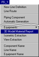
This operation can last few seconds at most for very big models and can be done at any time. It also shows some statistics about the model content.
To change the insulation or to insulate a part of a line that has no insulation, use the general command for Line Modification in the Line Utilities menu and change the Insulation Class of the selected components.
It is possible to Generate a 3D representation of the Insulation using the following command:
PD_UTI/General/Create 3D Insulation
or from the toolbar menu:

All components contained in the 3D Model are processed. For each insulated component a 3D insulation element is generated. It can have the same shape of the insulated piping component, or a different one depending on the paramenetric definition of the component itself.
With EPLANT-Piping it is very easy to assign Spools to prefabricate pipe lines. Each spool can be any alphanumeric code up to three characters long. They are assigned and revised interactively, the same for the pipe surplus at the spool ends.
 EPLANT-Piping Tutorial: Spools and Pipe Tolerance (3min 16sec)
Although working in a 3D model can result in almost no interference between different objects, there is a command that will automatically detect any interference. It can be selected in:
PD_UTI/Interference/Interference Checking
 EPLANT-Piping Tutorial: Interference Checking (37sec)
If enabled from the Project Setup in the dada base module, it is possible to place
components out of specification, although it is not a very good
practice, because the Piping Class Verification command cannot check those components
after their generation.
The sequence is the following: the Line Active Parameters are changed,
setting the required line and selecting the conventional class * that is
present in the class popup menu selection if the Out of Spec option is enabled.
During the component generation, the following input dialog will appear:
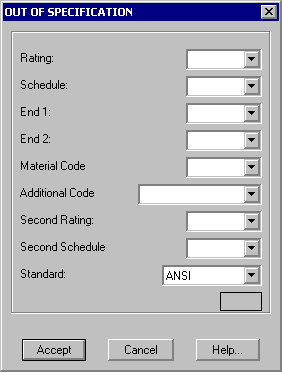
In this dialog all component parameters can be defined at will.
To delete a component generated with EPLANT the AutoCAD Erase command can be used, as any other element generated directly with AutoCAD.
To rotate a component the AutoCAD Rotate and Mirror command can be used or the EPLANT command that was used to rotate a valve operator:
PD_UTI/Component Rotate Axis
or from the toolbar menu:

To move components the AutoCAD Move command can be used, but only in the case that this component move is not creating a disconnection between components. Generally it is better to use the EPLANT command:
PD_UTI/Move Components
or from the toolbar menu:

This command allows to select the elements (they can be any AutoCAD elements) to move, the point that we want to move and the reference point that remain fixed. The selected elements are moved to connect the first point to the reference one. It is the most used command to repair connectivity errors and automatically rebuilds the implicit codes also.
During the development of a project, the lines that are already present in the model
can make difficult to see details in the working zone. Due that each line has
automatically assigned two layers (one for its line route and the other for its 3D
components) and each equipment is on a different layer, it is easy to display only the
most useful information at any time.
There is a set of handy commands to control layers visibility. The most used allows to
set on and off the line layers based in the line number:
PD_UTI/Display Layers/Lines LR/3D
or from the toolbar menu:

Executing it, the following window appears:
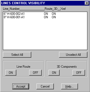
This window shows all lines ordered by name, giving the control to set on or off each individual line, both its line route and 3D components. All lines defined in the current file and in the attached files as XREF are displayed.
In: PD_UTI/Display Layers we can found other useful options. The most used are accessible from the toolbar menu:

These commands can be selected from:
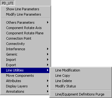
Line Modification opens a window to select the line to modify with two options:
Line Modification allows to modify any of the line definition
parameters, without changing any of the 3D components already generated. It can also be used
to merge a line with all its components to another existing line. To do this simply modify
the line name to that of the receiving line.
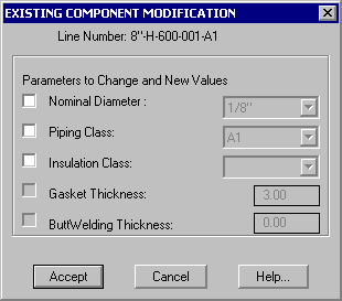
Component Modification In this case base characteristics of components already placed
can be modified, the corresponding line definition not withstanding. The parameters allowed
to change are seleted in the following window:
Line Copy allows to generate a copy of an entire line with another name.
In the case we need a mirror copy of a line with another name, the new line will
be copied with this command and next, using the AutoCAD command Mirror it can be
converted to its final shape.
Line Delete allows to permanently eliminate the graphical representation of a line and its internal definition. Deleting with the AutoCAD ERASE command, although it effectively deletes the components, can't eliminate the line definition.
Modify Status allows to assign a Status Code to each line to measure the project advancement. Similar to the same command used for Equipments.
Line/Equipment Definitions Purge allows to automatically delete all definitions
of Piping Lines and Equipments that no longer have any graphical element associated to
them.
It is used to extract a part of a 3D model. In this case the complete sequence is as
follows: the original drawing file is copied with another name, that new file is open,
all layers are set ON, only those layers containing Lines and Equipment that are to be
saved are set OFF, all visible elements are deleted, this command is then executed to
eliminate unwanted definitions.
 EPLANT-Piping Tutorial: Line Utilities (57sec)
Flow Direction can be set in any 3D line inserting the corresponding component, that must be connected to a pipe end. It is placed with the option:
PD_UTI/Generic/Flow Direction
During the isometric extraction, in the same position the corresponding symbol will be inserted.
Another option is to identify the First Component of the line using the command:
PD_1/Generic/Flow Direction/First Component
The First Component is used during the isometric extraction as a start point to draw the isometric; in the generation of Joint codes is where the numbering starts and in Extraction to PDMS it is the begining of the first branch of the line.
A reference to a Vertical Axis can be associated to any component, to be able to automatically dimension between the selected component and the reference axis in the isometric drawing. It is defined with the option:
PD_UTI/Generic/Vertical Axis Reference
The following dialog appears:
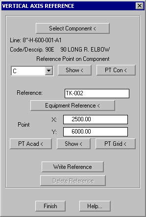
The reference can be either typed, selected as an Equipment or as a point defined by the intersection of two grid lines. Referer to the Help button for details.
The whole 3D models can be checked against P&IDs if the EPLANT-P&ID module has been used to draw them or, at least to manually load the EPLANT-P&ID data base module with the relevant data. From the Utilities menu in the Data Base module select:
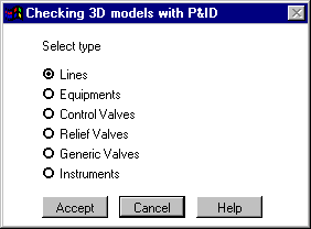
Selecting a Type and pushing the Accept button the command will be compare the selected object both in all 3D Models and in P&IDs, looking for inconsistencies that will be stored in text files in the DBF project directory.
This command give access to several related commands to place Typical Structures used
to support piping directly or through Supports. Supports are EPLANT Piping Components
connected to ther rest of the piping line, while Typical Support Structures are 3D blocks
either created with EPLANT-STH or by plain AutoCAD. They must be previously defined and
placed in the project /SUPP forlder.
Selecting:
PD_1/Generic/Support Structure
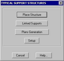
Selecting Place Structure, the following window will open:
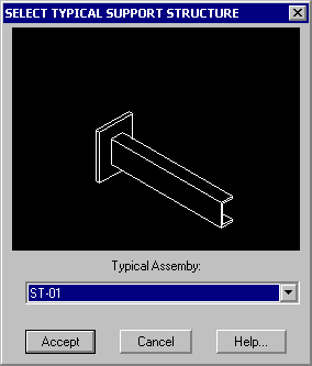
where in the men will appear all the drawing files placed in the project /SUPP folder.
If there is a slide with the same name of the corresponding dwg file, that slide will be
shown above the menu.
The selected structure is inserted in the 3D model as a block, specifying insertion point
and angle.
To link these structures with the corresponding Piping Supports, the Linked Supports
button is used:
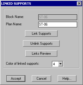
In this window the Plane Name is also defined, by default being the same as the block name
of the structure itself.
Three buttons: Link, Unlink and Review allow to manage the linking of the selected
structure with the corresponding supports.
The Setup button allows to define layers and texts.
Selecting the Plans Generation in the main window, the command prompts to select
the support structures for which the plan must be generated. For each block used as
structure there must be a corresponding template with the same name in the /SUPP/TEMPL
project folder. The drawing mus be a lateral projection in the XZ plane of the 3D support,
drawn in the XY plane of the template. Coordinate origin of the template must be homologous
to the 3D support model coordinate oring: X axis in the template relates to 3D X, Y axis
in the template relates to Z in the 3D model.
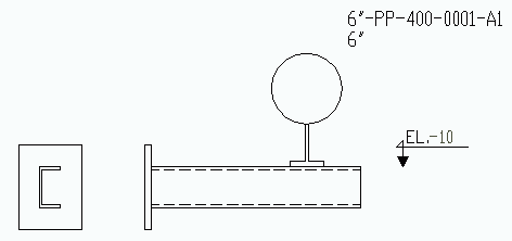
The template file is copied with the Plan Name to the /SUPP/OUT project folder and all
linked supports are drawn using the projection along local X axis defined in the
corresponding pdl files. Each pipe crossing the structure is also drawn as section.
Should the block ELEV being found in the template (defined as example in the TEST project),
the ELEV attribute defined in this block is then loaded with the global Z coordinate
corresponding to the local Y axis in the template.
Here below an example of a Template:

Example of corresponding 2D Plan, automatically generated:
Last updated April 24th, 2020.