
Once the equipments have been generated, we can start routing piping lines. The first thing to do is to generate the 8"-H-600-001-A1 line of our example as a new piping line, defining its name and other characteristics with the option:

The following dialog box will appear, where we'll load the parameters required by our example:
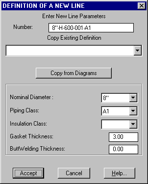
In this window all line parameters are defined. With respect to the line name, although any arbitrary name can be used, it is very convenient to respect the format specified in the project setup, to allow, among other things, isometric drawings be generated with a consistent name.
When all the parameters are loaded, we exit with the Accept button and a confirmation window will prompt to accept the creation of a new line definition. Upon accepting this option, a window with all line parameters will appear as confirmation.
From this moment the line 8"-H-600-001-A1 can be used to work with it.
 EPLANT-Piping Tutorial: Generation of Line 8"-H-600-001-A1 (26sec)
With the definition of the line already done, we can start the 3D piping design.
It is convenient at this point, to set an isometric view.
In case we want to use a Line Route as a reference to place 3D piping components on the
line, the following command is used:

that opens the following window to select the first point:

The four options are similar and the only difference among them is the selection method for the starting line point:
In the last three cases, if the Component Generation of the current Line
Active Parameters is set to Graphic Selection, the command continues the selected
line, otherwise it draws the Active Line.
A particular line can also be forced enabling the Use Line e selecting it in the
popup menu to the right.
The coordinates of all points are expressed in the current UCS.
In all the cases, the command prompts to select the first point and next opens the
following window to define the following points:
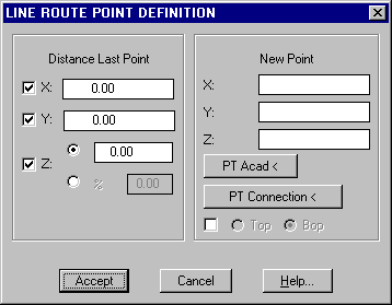
In Distance Last Point the new point relative coordinates, with respect to the
last point, are input. The elevation can be also expressed as inclination (%), while in
New Point, the same coordinates are expressed in absolute form with respect to the
current UCS. With the Accept button, the line route segment specified here is
generated and the same window is presented again. To stop drawing, exit with the
Cancel button.
In case of Point Selection (AutoCAD or Connection) if either the Top or Bop
option is selected, the Z coordinate of the selected point is modified to adjust it to
the Top or Bottom of the pipe, using the line diameter.
The detailed command sequence needed to route our example line can be followed below. We start selecting the Snap to Component End with the command:

The command prompts to select a Connection Point, that can be on a piping component or
an equipment nozzle, in the same drawing file or in an attached external reference
file. In our case we select the A nozzle of the TK-001 equipment.
The following line selection window will appear (because a nozzle was selected):
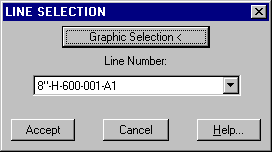
Selecting the 8"-H600-001-A1 line, the nozzle connection point will be snapped:

For the following points, we use this sequence:
Distance X = 0 , Distance Y = -500 , Distance Z = 0
Distance X = 2000 , Distance Y = 0 , Distance Z = 0
We continue with a point down to elevation 200: it is convenient to specify this value
as the Z coordinate of the New Point: X = 0 , Y = 0 , Z = 200
This sequence will be the most convenient to use if, between the flange connected to the A nozzle and the elbow, a pipe segment were to be needed. In our case, the elbow is directly connected with the flange, so we'll see in the next chapter, that a better sequence is to start placing the Flange and Elbow directly connected to the nozzle and from there, start drawing the Line Route.
Anyway, the aim now is to connect to the C nozzle of the TK-002 vessel. We can use
a combination of filters, enabling them in the following way: we select the C nozzle with
the PT Connection button and unmark the X and Z projections
in the Distance box, as to enable only the Y projection to be taken into account. Accept
this point.
With the PT Connection button select the C nozzle again, but this time we unmark
the X and Y projections in the Distance box, to force the Z projection only to be
used. We accept this point also.
At last, we select the C nozzle again, but this time without any filter (or with the X
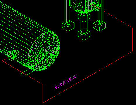
filter that is the same) to connect to the nozzle. The final geometry is the following:
 EPLANT-Piping Tutorial: Line Routing of Line 8"-H-600-001-A1 (1m 52sec)
Before to draw the 6" branch of the 6"-H-600-002-A1 line we must define this line which have the following characteristics:
Line Number : 6"-H-600-002-A1
Nominal Diameter : 6"
Piping Class : A1
Insulation Class : none
Gasket Thickness : 3.00
Butt Welding thickness : 0.00
Now we need to force the use of this line, because on the contrary, snapping for reference on the 8"-H-600-002-A1 line, this last line will be used for the routing of the branch side. As an alternate method, we could force the 002 line changing the Line Active Parameters also. We take the command

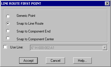
In the dialog box we select the Snap to Line Route option and we also make sure that our line 6"-H-600-002-A1 is selected and in the popup menu. We exit this dialog with the Accept button.
We can now start the branch routing. At the prompt to Select Line we select a point over the larger segment of the 8" line, on the TK-002 vessel side. The following message will appear:
Distance from end (total = 4451.5) <950.0>: 1000
Type 1000, to select the branch point with precision. The command then displays the following confirmation window:

We need to define only one point with a Distance along X = -5000 , Distance Y = 0 and Distance Z = 0.
Line Routes can be identified with the menu command:
PD_1 / Line Name
The graphic file will show up now as in the following image. Identification texts with line numbers have been added.
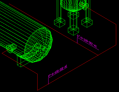
Opening a 3D model in which at least a piping line is defined, the so called Line Active Parameters are automatically assigned. The system uses them during line routing generation and component placement.
To display and modify the Line Active Parameters select the following option from the menu:

The following dialog box will appear:

The window is divided in two frames: in the upper part the Active Parameters are shown. Selecting an existing line, graphically or from the popup menu, the parameters associated with the selected line definition are updated. Each parameter can then be modified.
The frame COMPONENT GENERATION controls from where the Component Generation command gets the parameters needed for its generation:
The Line Route Reference parameter defines the geometrical reference used by the
line route when generating a component.
The most common case is Center: the line route represents the piping center line. The
other cases automatically generate the components moved by aligning its exterior diameter
to the top, bottom, front, rear side. These options are used when the best available
reference is not the center line.
The value of this parameter is always taken into account.
In case that project setup (General Options 2 button) allows defining Line and Equipment Attributes, the corresponding definitions is available in two different tables. For Lines, here an example:

In that case, the Line Name command will enable the Attribute button, where their values can be defined:
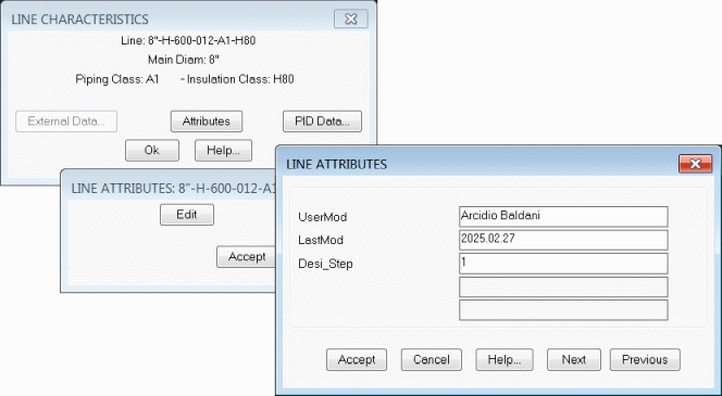
The values of the Line Attributes are available in the Line Table in the Data Base module, as well as, they are exported to Navisworks.
Last update May 06th, 2025.